

DISTRIBUTION CENTRAL

AREAS OF APPLICATION
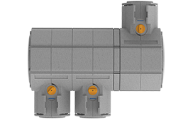
The air-lab modular distributor is designed for
central air distribution within the utilities room.
It works by feeding the incoming and outgoing
air for a specific zone to at least one modular
distributor, which then distributes this
air to the piping system.
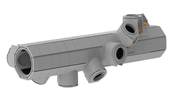
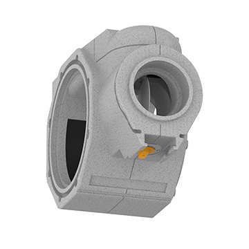
PRODUCT DESCRIPTION
This distribution system has a modular structure
and therefore permits infinite configurations.
All of the exterior casing parts are made of EPP,
which provides effective thermal insulation.
The module interfaces are designed in such a way
that the system pipes can be connected within a 45 degree grid along the distributor shaft.
This means that every distributor can be configured
in whatever way is best suited to the conditions on
site, including in areas with limited space.
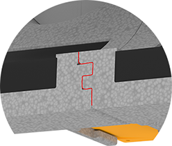
The individual modules feature double tongue and groove connections that interlock with each other.
They are furthermore sealed in two ways (with
seals and adhesive), which makes them
extremely leak-proof and strong.
Spacer ring K/K
Combined distributor module

Pipe section
Spacer ring K/S
Bypass module
Pipe
section
Cover
Spacer ring K/S
Double sleeve
Feed module
Combined distributor module
Cover
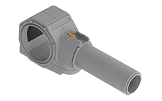
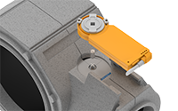
FEED MODULE
The feed module is designed for connecting
incoming and outgoing air pipes.
Double tongue and groove connection
i
Feed module 160 /
Feed module 200
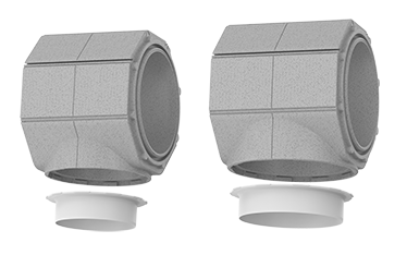
The flange connection has a bayonet lock, which means it can be fitted to the feed
module without any tools.
i
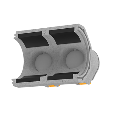
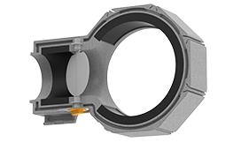
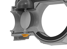
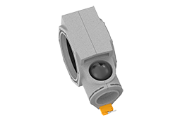
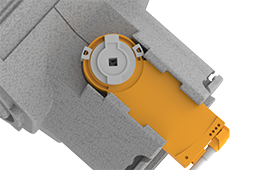
COMBINED DISTRIBUTOR MODULE
The combined distributor module is designed to distribute and regulate air flow to the individual
incoming and outgoing air pipe sections.
It features an integrated throttle valve that adjusts the module’s internal cross section to control air flow.
The combined distributor module is furthermore fitted with an acoustic foam insert in the distribution shaft
and pipe interface area in order to reduce noise.
SPACER RING K/S
The K/S spacer ring is designed for adjusting
the gap between two distributor modules.

BYPASS MODULE
The bypass module fulfils the same function
as the combined distributor module but is fitted
with a second mechanically-coupled flow restrictor.
This flow restrictor (bypass) can be used to introduce supply air into a single room at a different temperature.
The bypass module is furthermore fitted with an
acoustic foam insert inside the distribution shaft.

Throttle valve
i
Double tongue and groove connection
i
Tongue and groove connection for connecting the pipe section
i
Acoustic foam insert
i
Acoustic foam
insert
i
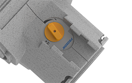
Dial for adjusting the throttle valve
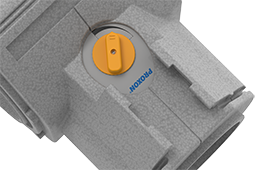
Connector for electrical actuator

i
Throttle valve
i
Double tongue and groove connection
i
Bypass section with connection at the back

Alternative: Bypass section with connection at the front
i
Acoustic foam insert
i
Dial for adjusting the
throttle valve and
flow restrictor
Connector for electrical actuator
i
Flow restrictor (bypass)
i
Tongue and groove connection for connecting the pipe section
i

i
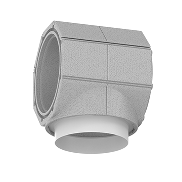
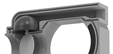
SPACER RING K/K
The K/K spacer ring is used to make the distributor modules point in different directions
while ensuring that all of the throttle drives are
on the same side.

i
COVER
The cover is used to seal off both or either
side of the distribution shaft.

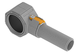
PIPE SECTION
The pipe sections are designed for use as air ducts within utility rooms.
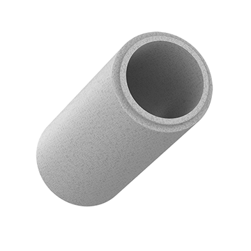
The individual sections can be joined to form longer pipes by their key and slot connections.

i
Key and slot connection for connecting a pipe section to a combined distributor or
bypass module
Alternative: Key and slot connection for connecting another pipe section
i
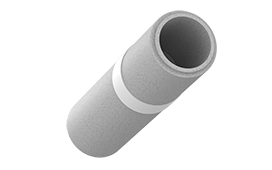
DOUBLE SLEEVE
The double sleeve is designed for connecting
two pipe sections that have been shortened.

Connector for a shortened pipe section
i
TECHNICAL DATA
A PDF with product variations and technical data can be downloaded by clicking the following link:
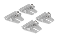
ACCESSORIES
● Installation kit (Art. no. 70288)
Installation example:
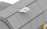
● Shaft extension (art. no. 10522)
Required when using electrical actuators
Installation example:


+49 (0) 2764 261 35 - 0
+49 (0) 2764 261 35 - 20